- Welcome to Westlake Publishing Forums.

News:
REGARDING MEMBERSHIP ON THIS FORUM: Due to spam, our server has disabled the forum software to gain membership. The only way to become a new member is for you to send me a private e-mail with your preferred screen name (we prefer you use your real name, or some variant there-of), and email adress you would like to have associated with the account. -- Send the information to: Russ at finescalerr@msn.com
Recent posts
#11
Modellers At Work / Re: Luke's Garage & Gas Statio...
Last post by Hydrostat - March 30, 2025, 12:46:24 PMQuote from: Ray Dunakin on March 23, 2025, 10:54:49 PMIt looks great! I love those tires and spoked wheels. The handmade oil drum is fantastic! I tried making a 1/24th scale oil drum that way, using brass. It didn't work very well. I'll have to give copper a try.
I second that. Especially the tires are looking very good.
Cheers,
Volker
#12
Modellers At Work / Re: Hulett Ore Unloader in 1:3...
Last post by Hydrostat - March 30, 2025, 12:44:24 PMBernhard,
this is so well executed - I'm overwhelmed!
Volker
this is so well executed - I'm overwhelmed!
Volker
#13
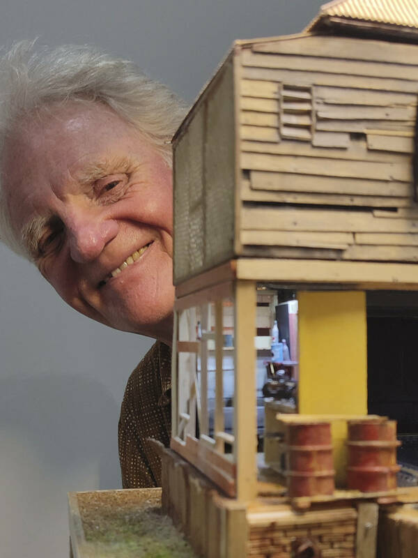
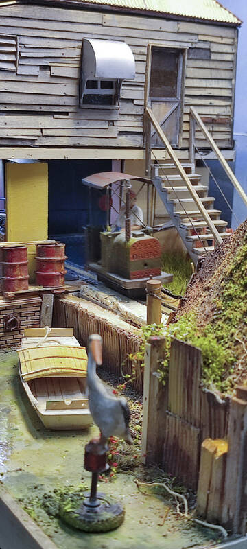
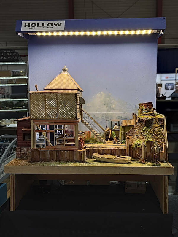
Modellers At Work / Re: Sandy Hollow
Last post by Hydrostat - March 30, 2025, 12:42:47 PMKim,
it was a pleasure to meet you and see Sandy Hollow last week at the 'Internationale Spur 0 und Spur 1 Tage in Gießen'!
Cheers,
Volker
it was a pleasure to meet you and see Sandy Hollow last week at the 'Internationale Spur 0 und Spur 1 Tage in Gießen'!
Cheers,
Volker
#14
General Forums / Re: San Juan Model Company
Last post by finescalerr - March 29, 2025, 12:26:31 AM"Doug" is Doug Junda, one of the owners. I don't know why he's not getting back to you. Maybe he's out of town. -- Russ
#15
General Forums / Re: San Juan Model Company
Last post by Lawton Maner - March 28, 2025, 02:23:38 PMCalled, got a recording and a suggestion that I send an email to "Doug", did so and no response.
#16
General Forums / Re: San Juan Model Company
Last post by TRAINS1941 - March 24, 2025, 08:01:26 PMI just ordered Grandt Line NBW's from them. Had them is 5 days.
Jerry
Jerry
#17
Modellers At Work / Re: Luke's Garage & Gas Statio...
Last post by Kevin Sikorsky - March 24, 2025, 02:13:49 PMNice work
#18
Modellers At Work / Re: Annoying HO Project
Last post by Kevin Sikorsky - March 24, 2025, 02:10:17 PMHey there Russ. Ya know. Everyone picks apart their own builds. In a way I guess, it's the only way to successfully build. But plain and simple, it's always great to build. Don't lean so hard on this one. I like it. And paper - in HO, it's even better.
#19
Modellers At Work / Re: Hulett Ore Unloader in 1:3...
Last post by Peter_T1958 - March 24, 2025, 12:13:50 AMQuote from: Bernhard on March 23, 2025, 09:39:11 AMAs a next step, I have decided to tackle the second carrier. As long as I still have some idea of how I built the first one.
I am simply overwhelmed. Such a professional approach - and furthermore very forward planning! It's actually a fact, that modelling skill or the knowledge about how something was made fade away. To my experience that knowledge is stored not only in our memory but also in our hands etc. (comparable with the skill to jump from a springboard). So you should do well tackle down the second carrier now !
#20
Modellers At Work / Re: Hulett Ore Unloader in 1:3...
Last post by Ray Dunakin - March 23, 2025, 10:58:14 PMI can't get over how massive this thing is going to be!